 English
 Türkçe
 Russian
 Azerbaijan
 Spanish
 French
 German
 Arabic
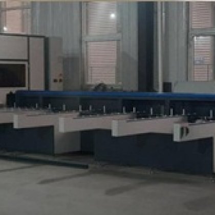
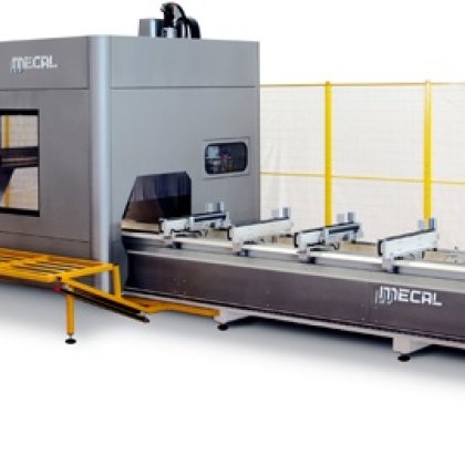
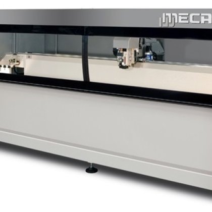
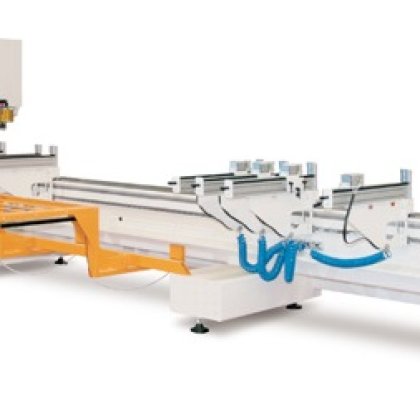
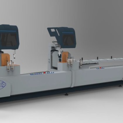
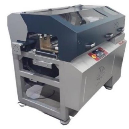

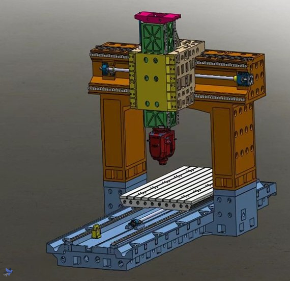
Gantry Machining Center : This machine tool is a high-rigidity, high-precision gantry machining center, specifically designed for processing various steel and aluminum parts. It operates smoothly and with precise positioning. In line with the characteristics of machining and the demands of modern high-precision and high-efficiency processes, this machine tool is designed and manufactured using integrated mechanical, electrical, and hydraulic technologies, along with new technologies in modern machine tool development. It can perform both rough and precision machining, demonstrating strong, efficient, and continuous machining capabilities during roughing. During precision machining, it ensures superior surface quality and accuracy. The machine tool's overall structure is designed using the internationally advanced finite element method in collaboration with Southeast University, offering excellent load-bearing capacity, scientifically distributed stress, and high stability. The design ensures ample overload margin and a high safety factor, making it highly resistant to impact and capable of operating continuously for three shifts without stopping. The machine tool boasts a high-rigidity structural design, reliable stability and retention, and comprehensive accessories. Its parts are modularly designed with a high standardization level, offering excellent interchangeability and consistent quality. The machine tool is advanced in design, reliable in performance, easy to operate, and convenient for maintenance. Additionally, the machine tool incorporates advanced European equipment and processes, featuring a high-rigidity frame structure that not only facilitates robust cutting but also meets the machining needs of precision components.
1. High rigidity structure
(1) The bed is made of precision HT300 high-quality resin sand cast iron. After secondary aging treatment with thermal aging and vibration aging. The overall structure of the machine tool consists of a closed rigid frame structure consisting of a bed, double columns, and fixed crossbeams. The workbench moves longitudinally along the bed guide rails (X-axis), and is equipped with a vertical high-power multifunctional sliding pillow milling (boring) head on the fixed crossbeam. The milling and boring head slide moves horizontally along the crossbeam guide rails (Y-axis) and the sliding pillow boring and milling head moves up and down (Z-axis)
(2) The main basic components of the machine tool, such as the bed, workbench, column crossbeam, lateral sliding plate, milling head slider, etc., are all made of high-strength cast iron and resin sand molding, which has good shock absorption, thermal stability, and high structural strength and rigidity of the entire machine. The Y-axis two guide rails are designed and optimized using finite element analysis to achieve maximum rigidity and stability.
(3) The door frame of the machine tool is an integrated casting structure, with excellent rigidity.
(3) The design of a wide base and two X-axis guide rails makes the machine tool stable like a rock, with excellent rigidity.
(4) The standard nitrogen balance greatly reduces the thermal extension of the Z-axis screw, thereby improving the processing quality.
2. High precision and high specification screw
(1) The three-axis machine tool is equipped with Japanese THK screws as standard, and hollow screws can also be selected for maximum protection
Verified the accuracy of the machine tool.
(2) The diameter of the three-axis screw of the machine tool is 80/63/63mm, and the lead is 20/12mm.
(3) The three-axis servo is connected directly to the screw, greatly controlling the conduction gap.
3. High precision heavy-duty guide rail
(1) The X-axis adopts two 55mm heavy-duty roller guides to ensure heavy load.
(2) The Y-axis adopts three 55mm heavy-duty roller guides, ensuring the stability of Z-axis movement.
(3) The Z-axis adopts two 55mm and two 45mm strips, ensuring the smoothness and high rigidity of heavy load re cutting.
4. Comprehensive testing
(1) The machine tool adopts RENISHAW's laser interferometer and ball and rod tester from the UK to ensure linear motion of the machine tool
Accuracy and dynamic response performance. The spindle and spindle motor are dynamically balanced by a spindle vibration meter to ensure the smoothness of high-speed motion.
5. Beautiful, high-end, and safe electrical design
(1) The electrical design fully complies with CE standards. The use of imported cables effectively reduces the impact of electrical interference, while also adopting
Using European circuit design and manufacturing standards, the electrical appliances are stable and easy to maintain.
6. Tool cooling system
(1) The tool cooling system adopts an external circulation method, and the coolant flows into the chain plate elevator at one end of the bed through the spiral chip removal groove on both sides of the bed. After filtration and separation, the coolant flows into the coolant box on the elevator, and then is transported to the cooling nozzle at the spindle position by the coolant electric pump.
7. Smooth chip removal system
(1) The machine tool bed is equipped with spiral chip conveyors on both sides, which can transport the processed iron chips to the chain plate lifting device at the front end of the machine tool bed. The lifting device is equipped with a cutting fluid water tank, which is equipped with a high head coolant pump. The high head water pump transports the purified cutting fluid to the end of the spindle, which has multiple cooling nozzles. The cooling nozzles spray the cutting fluid onto the tool to cool it. The debris is collected by the elevator and transported to the recycling truck.
8. Lubrication of machine tool guide rails
(1) The lubrication of each axis guide rail adopts a central integrated self timed quantitative lubrication system, which is automatic lubrication and may experience pressure loss
And oil shortage safety protection.
9. Protection form
(1) The X-axis guide rail of the machine tool is protected by a stainless steel telescopic protective cover.
(2) The Y-axis guide rail of the machine tool is protected by a telescopic organ protective cover.
(3) Install maintenance ladders and protective railings on the gantry frame.
(4) The X, Y, and Z axes are equipped with drag chain protection devices.
10. CNC system
(1) The CNC system adopts the Japanese HEIDENHAIN TNC640 model or Siemens D828 D842, Fanuc i30, i0, with a standard tool tip following, which is particularly suitable for the processing of molds and aviation structural components.
11. Electric control auxiliary device
(1) Fully enclosed constant temperature electrical cabinet, standard protection, sealed and dustproof, equipped with lighting inside the electrical box.
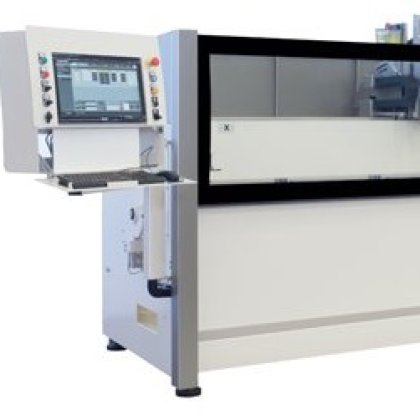
(2) The main operation station can conveniently perform various operations and controls, and is equipped with an electronic handwheel. The machine tool is equipped with servo system overload automatic protection and alarm devices, as well as mechanical power outage protection devices.
(3) Set software limits for each motion axis of the machine tool.
Notes:
(1) Machine tool power demand: 80KVA, the machine tool has leakage protection and power outage protection.
(2) Three color indicator lights for the working status of the machine tool.
(3) The machine tool noise meets national standards.
(4) Three phase AC power supply: 380V ± 10%, -15%; 50Hz ± 1Hz.
(5) Environmental temperature: 10-30C º.
(6) Relative humidity: ≤ 80%.
Air source pressure: 0.6~0.8 MPA
TNC 640 CNC System
Intelligent solutions meet demanding application requirements
24 control loops (22 with safety features), including up to 4 spindles
Multi touch display screen version
Milling, turning, and grinding processes
User friendly HEIDENHAIN Klartext conversational programming or G-code programming
Rich processing and detection cycles
High speed program segment processing speed (0.5 ms)
High performance, high surface quality, and high precision
Dynamic collision monitoring function, higher safety and reliability
Detailed parameters
CNC System HEIDENHAIN TNC640
(2) Display: English 19″
(3) CFCF card interface, portable operating system
2. Work trip
(1) x (x-axis) 3100 mm
(2) y (y-axis) 2200 mm
(3) z (z-axis) 800 mm
(4) (Spindle nose to table) 150~800 mm
3.
(1) (Table size) 3000X1500 mm
(2) (Max. loading capacity) 8 t
(3) T (Size of T-slot) 28x200x7 mm
(4)(Width between two columns) 1700 mm
4. (SPINDLE) T70 HEIDENHAIN MEPRO
(1) (Spindle speed) 10000 rpm
(2) (Spindle taper) HSK-A100
(3) (Spindle motor) 54 kw
(4) S1(Spindle torque) 200 n.m
(5)4(Spindle center water cooling) 3 mpa
(6) A(A Axis Rotation Range) -110-+110
(7) C(C Axis Rotation Range) -360-+360
5. (SLIDE WAY)
(1) x (x-axis) (2guide rail) 55X2 P
THK ( THK Japan) mm
(2) y (y-axis) (3guide rail) 55x3P
THK ( THK Japan) mm
(3) z (z-axis) (4guide rail) 55x2+45*2P
THK ( THK Japan) mm
6. (Driving screw)
(1) (Ball screw accuracy) C3
(2) (Ball screw diameter x.y.z) 80/63/63(THK) mm
(3)(Three-axis lead) 20/12 mm
(4)(Motor connection) (Connected through a coupling)
(5)(Number of bearings at both ends) 8/7/6 pcs
7. (Three-axis motor)
(1) x (x zaxis motor) 11KW 62 n.m
(2) y (y zaxis motor) 9KW 47 n.m
(3) z (z zaxis motor) 9KW 47(brake) n.m
8. (FEED RATE)
(1) X (x axis rapid feed rate) 12000 mm/min
(2) Y (Y axis rapid feed rate) 12000 mm/min
(3) Z (Z axis rapid feed rate) 12000 mm/min
(4) (Three-axis cutting feed rate) 0-10000 mm/min
9. ( tool )
(1) (Max. tool length) 300 mm
(2) (Max. tool dia) Ø120 mm
(3) (Max. tool weight) 8 kg
(4) (Tool specification) HSK
(5) (Maximum number of tools) 24 pcs
(6) (Tool change time) 6 s
10. (VDI/DGQ3441)
(1) (Positioning) 0.010/1000 mm
(2) (Repeat positioning) 0.006/1000 mm
(3) (Least input increment) 0.001 mm
10.
(1) (Power Capacity) 100 kva
(2) (t weight) 30 t
(3)(Packing 8000x3400x4500 mm
| Shop Location | yesil sokak cevizli 34847, Istanbul, Turkey |
No reviews found!

No comments found for this product. Be the first to comment!